Cabinetmaker. In 1921 he became one of the founders of the Communist...

Sometimes the designer has to draw a plan of the excavation, in fact, this is the simplest drawing - with a minimum of lines and symbols. Now let's take an example of how to draw a pit.
Let's start with slopes. Vertical slopes are allowed by the norms very rarely (with a pit depth of less than 1.5 m for certain types of soils). For different types of soil, a different slope is normalized, which is directly related to the angle of internal friction. What is the angle of internal friction? If it’s rough, then a pile of soil, poured in a cone at an angle of internal friction, will not tend to crumble - the soil holds itself. If you try to make the angle of the cone steeper, then the soil will “go”, this is fraught with collapse, and in the case of a foundation pit, collapse means possible human casualties.
If you are not limited in terms of the dimensions of the site, existing structures and communications, you can safely make slopes of the pit at an angle of 45 degrees - this angle is almost always acceptable (except for bulk soils). More gentle angles are not rational - and they take up a lot of space, and there is more work for excavation. Steeper angles should be checked in the literature (whether they are acceptable for a given type of soil).
Below is a table from SNiP III-4-80 "Safety in Construction" (in Russia it has been replaced by a newer one).
The 1:1 ratio is 45 degrees (when the width of the slope in the plan is equal to the depth of the pit). The ratio of 1:05 is a steeper slope at 60 degrees (when the depth of the pit is twice as large as the width of the slope in plan), the ratio of 1:1.25 is more gentle (for bulk uncompacted soils with a pit depth of 5 m or more).
Remember, if the site on which you are designing the foundation is constrained by some circumstances, always before starting the design, you need to think over the process of earthworks, so that later it does not turn out that the house cannot be built at all.
Example 1. The simplest case. The plot is flat, the absolute mark of the existing soil is 51.30. For the mark of 0.000 in the project, the mark of 52.07 is conventionally accepted. The elevation of the bottom of the foundation slab is -3,000. Under the slab, a preparation of concrete with a thickness of 100 mm is provided. The construction site is not constrained by anything, the soil is loam.
By the way, please note that absolute marks are usually indicated with two decimal places, and relative marks with three.
Let's determine the absolute mark of the bottom of the foundation slab: 52.07 - 3.0 = 49.07 m.
Let's determine the absolute mark of the bottom of the pit (the bottom of the preparation): 49.07 - 0.1 \u003d 48.97 m.
Pit depth: 51.30 - 48.97 \u003d 2.33 m.
We accept the most convenient slope angle of the pit - 45 degrees.
1. We apply a grid of extreme axes and the contour of the foundation of the pit.
2. We retreat from the contour of the foundation outward 100 mm, thereby obtaining the contour of the preparation.
3. We retreat from the preparation contour to the outside 500 mm - the permissible minimum before the beginning of the slope, specified by the standards (previously it was 300 mm). This will be the contour line of the bottom of the pit.
4. We retreat from the contour of the bottom of the pit 2.33 m (depth of the pit) - because. slopes at an angle of 45 degrees, then the size of the slopes in the plan is equal to the depth of the pit. This will be the top line of the slope. We put on it a symbol for slopes in the form of alternating short and long lines perpendicular to the contour.

5. We remove all unnecessary lines (foundation, preparation contour), mark the bottom of the pit and mark the existing land.
6. We apply the missing dimensions - binding the corners of the pit to the axes.
7. Add a note about the correspondence of relative marks to absolute ones.
8. Optionally, we make a cut (we designate marks and slopes of slopes on it).

There is no need to develop an entrance to the pit, this is the concern of the POS (construction organization project), i.e. separate money.
Example 2. The same excavation, only soil with a slope in one direction (the absolute elevations of the existing earth are shown in the figure below). For the mark of 0.000 in the project, the mark of 52.07 is conventionally accepted. The elevation of the bottom of the foundation slab is -3,000. Under the slab, a preparation of concrete with a thickness of 100 mm is provided. The soil is loam, the slopes need to be made as steep as possible.

So, we have a ground drop in one direction - from 53.50 to 51.70 m, while on the survey the marks are indicated at specific points on the plan.
In such a situation, it is easier to start with a section of the pit.
Let's translate the absolute marks we have into relative ones.
The absolute mark of 53.50 m corresponds to the relative 53.50 - 52.07 = 1.430 m.
The absolute mark of 51.70 m corresponds to the relative 51.70 - 52.07 = -0.370 m.
The elevation of the bottom of the pit is -3.100 m.
The easiest way to see the algorithm for building a pit will be on the video.
As you can see, everything is not so difficult. And the drawing in the end will look like this.

Many people never think about what it should be like when excavating, regardless of their purpose. But building your own house without land development is almost unthinkable. Trenches for strip foundations, or drainage devices - all these earthworks must be carried out not only taking into account the technological requirements of the structures that will be laid in them, but also in compliance with safety standards. As practice shows, even the slightest neglect of compliance with the requirements regarding the width of the trench often leads to quite serious consequences, which could have been avoided quite simply.
How most of the time most of us determine what should be? What would be convenient to work below - this is the answer that is the most common. Yes, the width of the trench in its lower part must meet this requirement, so it depends on the diameter of the pipeline that will be laid in the finished trench, as well as the method of laying the pipes.
Now you know how to determine the width of the trench, based on the diameter of the pipeline laid in it. But often this is not enough. The fact is that the width of the trench in its upper part also depends on the type of soil in which excavation is carried out.
Each type of soil has its own properties, which include the angle of natural collapse. This official wording implies that with a significant depth of the trench, the soil can collapse due to insufficient adhesion of its particles, moreover, the collapse zone for each type of soil is quite individual. Therefore, there is a table that indicates the values \u200b\u200bof the permissible steepness trench slopes for the main types of soil, under which the risk of soil collapse is practically absent. Using this table, depending on its depth and type of soil, you can determine the optimal trench width in its upper part.

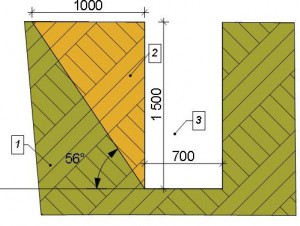
I think this table needs some explanation. The slope angle of each type of soil in this table is indicated relative to the lower horizontal surface of the trench, as shown in the diagram. In addition to the angle value, the ratio of the slope height to its horizontal projection is also indicated. Let's take as an example the situation with bulk soils, which are the most dangerous when excavating due to the low adhesion of its particles to each other.
With a trench depth of 1.5 meters, the angle trench slope according to the table should be 56 °. The distance from the point of intersection of the corner line with the soil surface to the beginning of the trench in this case is 1 meter, which corresponds as 1:0.67. If the depth of 1.5 meters is multiplied by 0.67, we get 1.005 meters. It is at this distance that the trench slopes from its intended vertical walls, otherwise the risk of soil collapse is very high, and this is not only the loss of materials or the re-excavation, but also a threat to your life or the life of workers working in the trench. (Notation on the diagram: 1-soil; 2-possible collapse zone, which should be included in the slope; 3-theoretical size of the trench).
As can be seen from the table, clay, loam and bog loam are the best in terms of adhesion of soil particles to each other. If your site has just such soils, you are lucky in this case. If you have mobile soils, in order not to turn deep trenches into pits, their vertical walls need to be strengthened. How this is done, I will tell in the next post.
Permissible steepness slopes of trenches and pits
Excavation depth, m |
||||||
Characteristic | 3.0 to 5.0 |
|||||
Angle between slope direction and horizontal, deg. | The ratio of the height of the slope to its inception | Angle between slope direction and horizontal, deg. | The ratio of the height of the slope to its inception |
|||
Bulk natural moisture | ||||||
Sandy and gravel wet but not saturated | ||||||
Clay natural moisture content: | ||||||
loam | ||||||
Loess dry | ||||||
Notes: 1. If the excavation depth is more than 5 m, the steepness of the slopes is determined by calculation.
2. The steepness of slopes in waterlogged soils should be reduced against the values \u200b\u200bspecified in the table to 1:1 (45 °).
3. It is forbidden to develop waterlogged, sandy, loess-like and bulk soils without fastenings.
20.8. Fastening of the vertical walls of trenches and pits should be carried out with shields in accordance with the instructions given in Table 15.
Table 15
Fastening the walls of pits and trenches depending on the soil
Types of vertical fasteners walls of pits and trenches |
|
Natural moisture, except for free-flowing | Horizontal fastening with clearance through one board |
High humidity and loose | Solid vertical or horizontal mounting |
All types with a strong influx of groundwater | Sheet piling below the groundwater horizon with driving it to a depth of at least 0.75 m into the underlying waterproof soil |
20.9. Fastening of pits and trenches up to 3 m deep, as a rule, should be inventory and carried out according to standard projects. In the absence of inventory and standard parts for fixing pits and trenches up to 3 m deep, the following should be done:
20.9.1. Use boards with a thickness of at least 4 cm in sandy and high humidity soils, laying them behind vertical racks as they deepen;
20.9.2. Install fastening racks at least every 1.5 m;
20.9.3. Spacers should be placed at a vertical distance of no more than 1 m from one another; under the ends of the spacers (top and bottom), nail the bosses;
20.9.4. Produce upper fastening boards above the edges of the recesses by at least 15 cm;
20.9.5. Strengthen the fastenings (struts) on which the shelves intended for soil transfer rest, and protect these shelves with side boards at least 15 cm high.
20.10. Fastening of the vertical walls of pits and trenches with a depth of more than 3 m should be carried out, as a rule, according to individual projects.
20.11. The dismantling of fasteners must be carried out under the direct supervision of the Responsible Worker.
Dismantling should be done from the bottom up as the soil is backfilled.
20.12. When performing earthworks, it is necessary to ensure systematic monitoring of the state of the soil of trenches and pits.
20.13. If large stones are found in the slopes, workers must be removed from dangerous places, and the stones should be lowered to the bottom of the slope or removed.
20.14. The chambers and sections of underground heat pipelines opened for the production of work must be closed with strong and dense shields or fenced.
20.15. Through trenches and pits dug on platforms, driveways, walkways and in other places of movement of people, transitions should be arranged with a width of at least 0.7 m, fenced on both sides with railings with a height of at least 1 m with sheathing along the bottom of the sides with a width of at least 10 cm .
20.16. To descend into trenches, pits should only be by stairs.
20.17. If there are electric cables in the excavation sites, it is impossible to use impact tools: crowbar, pickaxe, pneumatic shovels, etc. Work should be carried out in the presence of a cable network worker, taking care to prevent damage to the cable and electric shock to workers.
20.18. When the cable is exposed, it is necessary to hang it to avoid rupture; it is strictly forbidden to stand on the cable. If the work is long, the cable must be sewn into a wooden box. Posters should be hung on the boxes covering the excavated cables: "Stop: high voltage" or "Stop: life threatening."
20.19. Throwing tools or material into the pit is prohibited. It must be lowered on a rope or passed from hand to hand. It is forbidden to stay under the load lowered into the pit.
20.20. If the smell of gas is detected during earthworks, work must be immediately stopped, and workers removed from dangerous places until the causes of gas are found out and eliminated.
Further performance of work with the possibility of the appearance of gas is allowed only if constant monitoring of the state of the air environment is ensured and workers are provided with the necessary number of gas masks.
Workers in this case, before starting work, must be instructed on the procedure for performing work in a gassed area.
20.21. To avoid an explosion, smoking, working with a blowtorch and other devices related to the use of open fire in trenches near which a gas pipeline is located or gas accumulation is possible is prohibited.
20.22. Areas where electric heating of the soil is carried out must be fenced, and warning signals must be hung on the fences. At night, the heated area should be lit.
For electric heating of soil of natural moisture, a voltage of not more than 380 V is allowed.
20.23. In areas under voltage, it is prohibited to stay by unauthorized persons.
Electric heating must be serviced by an electrician with the appropriate qualification group.
20.24. Temporary lines from the transformer to the heated areas must be carried out with an insulated wire of the appropriate section, laid on the goats with a height of at least 0.5 m from the ground.
20.25. When heating the soil with flue gases, hot water or steaming, measures must be taken to protect workers from burns.
20.26. When surface thawing of soil using hot gas, it is necessary to take measures to prevent poisoning of workers and gas explosion.
20.27. The organization that performs the work is responsible for the safety of work carried out on the route of existing heating networks, and these works are allowed to be carried out only after agreement with the organization operating or owning these networks.
21. SAFETY REQUIREMENTS FOR HANDLING SOURCES OF IONIZING RADIATION
21.1. Works with radioactive substances and sources of ionizing radiation are carried out with the permission and under the control of the state nuclear supervision and sanitary and epidemiological supervision bodies, which must be provided with all the necessary documentation on the nature of the work performed, the radiation situation in the organization and on the adjacent territory.
21.2. Radioactive isotopes used in production are sources of radiation various kinds that have harmful effects on the human body. As a result of ionization of adipose tissue, which consists of 70% water, molecular bonds are broken and the chemical structure various compounds, which leads to cell death.
21.3. The nature of the damaging effect of radioactive radiation depends on a number of conditions: the type of radiation (-, -, -, neutron radiation), its activity and energy, the life of the isotope (half-life), internal or external exposure, exposure time, etc. .
21.4. The main task of radiation safety, which ensures the protection of people from the harmful effects of ionizing radiation, is the exclusion of any unreasonable exposure; reducing the radiation dose to the lowest possible level and not exceeding the established basic limit. The main document regulating the levels of exposure to ionizing radiation on humans is NRB-96.
21.5. According to the permissible basic dose limits, the following categories of exposed persons are established:
Table 16
GN 2.6.1.054-96
Basic dose limits
Normalized values | Dose limits |
|
Members of staff* (Group A) | Persons from the population |
|
Effective dose | 20 mSv*** per year on average for any consecutive 5 years, but not more than 50 mSv per year | 1 mSv per year on average for any consecutive 5 years, but not more than 5 mSv per year |
Equivalent dose per year in the lens | ||
bones and feet | ||
Notes: * - exposure doses, like all other permissible derivative levels of group B personnel, should not exceed 1 / 4 values for group A personnel;
** - refers to the average value in a layer with a thickness of 5 mg/cm 2 . On the palms, the thickness of the cover layer is 40 mg / cm 2 ;
***- 1 mSv (milisievert) = 100 mrem (milirem);
One Sievert (Sv), which is a unit of equivalent dose in SI, is equal to the equivalent dose at which the product of the absorbed dose in biological tissue and the average quality factor K (K=1 - for beta particles and gamma radiation; K=3 - for neutrons with energy less than 0.03 MeV; K=10 - for neutrons with energy 0.03-100 MeV (fast neutrons); K=20 - for alpha particles) is equal to 1 J/kg.
21.5.2. The entire population, including persons from the staff, outside the scope and conditions of their production activities.
21.6. Permissible radioactive contamination of work surfaces, leather, overalls, footwear, personal protective equipment for personnel are given in Table 17.
Table 17
GN 2.6.1.054-96
Permissible levels of general radioactive contamination of work surfaces, skin
(during the work shift), overalls and personal protective equipment, part / (min * cm 2)
Object of pollution | Alpha active nuclides | beta active |
|
individual | |||
1. Intact skin, special underwear, towels, the inner surface of the front parts of personal protective equipment | |||
2. Basic overalls, the inner surface of additional personal protective equipment, the outer surface of safety shoes | |||
3. Surfaces of premises for permanent residence of personnel and equipment located in them | |||
4. Surfaces of premises for periodic stay of personnel and equipment located in them | |||
5. The outer surface of additional personal protective equipment, removed in the sluices | |||
21.7. When using sources of ionizing radiation in work, the employer is obliged to ensure the radiation safety of these works and organize control over the state and ensuring radiation safety.
21.8. The administration of an organization that uses sources of ionizing radiation in its work is obliged, taking into account the specifics of the work performed with sources, to coordinate with the local bodies of state nuclear supervision and sanitary and epidemiological supervision and approve the regulation on the radiation safety service of the organization.
21.9. The tasks of the radiation safety service of the organization should be:
control over compliance with the rules, norms and requirements of radiation safety;
control over the state, accounting, storage, receipt, issuance, transportation and use of sources of ionizing radiation;
control over personnel exposure doses;
control over the admission of personnel to work with sources of ionizing radiation, over training, instructing personnel;
control over emissions into the environment and the general background radiation in the organization, over the level of radiation contamination of premises, equipment, overalls and other personal protective equipment, skin, personnel clothing, the quality of their decontamination, etc.;
providing the administration of the organization with the necessary information on the state of radiation safety in the organization;
control over all types of work with sources of ionizing radiation;
control over compliance with radiation safety requirements in relation to products manufactured by the organization, etc.
21.10. Employees of the radiation safety service must be from among the personnel directly working with sources of ionizing radiation (category A), must have an appropriate certificate of special training, be proficient in control and measurement methods to the extent necessary to perform their functions.
21.11. In its work, the radiation safety service must be guided by the current legislation and regulatory legal acts on radiation safety.
21.12. Instructions and instructions of the radiation safety service of the organization to eliminate the identified violations are mandatory for execution within the time limits established by the chief engineer (technical director).
21.13. The employer is responsible for the state of radiation safety in the organization.
21.14. The main methods of protection against ionizing radiation are:
distance protection (irradiation intensity decreases in proportion to the square of the distance), therefore, remote control should be used when working with sources of ionizing radiation;
time protection (reduction of contact time with a source of ionizing radiation), therefore, work must be carried out in a strictly organized manner within a short time frame;
shielding protection (sheltering a source of ionizing radiation in containers and other structures made of materials that absorb radiation well (lead, concrete, glass, and other materials)).
21.15. When working with ampoules with radioactive substances, external exposure is possible. Therefore, work with ampoules requires special measures to protect against radiation.
21.16. In emergency cases, when the integrity of the ampoule may be violated, special measures must be taken, including fencing the danger zone with radiation hazard signs, beyond which the radiation power does not exceed the permissible norm.
21.17. Particular attention in the organization should be given to the storage and transportation of sources of ionizing radiation. Such substances are transported in lead containers on special vehicles, equipped with radiation hazard signs.
21.18. Persons not younger than 18 years of age who have undergone appropriate training, medical examination and dosimetric control may be allowed to work with radioactive isotopes.
21.19. The nature and organization of dosimetric monitoring depend on the type of work performed. Radiometers control the level of cleanliness of the hands, clothing and body of workers and work surfaces. Dosimeters determine the dose or dose rate of radiation in roentgens or rems. The results of dosimetric monitoring should be recorded in special journals and radiation dose records, which should be entered for each employee working in contact with sources of ionizing radiation.
danger. Organizationholding. SWEATRO14000 -005 -98 Approved Department of Mechanical Engineering Economics of the Ministry of Economy...As a result of earthworks, earthworks are created, which are classified according to a number of criteria.
According to the purpose and duration of operation, earthworks are divided into permanent and temporary.
Permanent structures are designed for long-term use. These include canals, dams, dams, planned sites for residential areas, complexes of industrial buildings, stadiums, airfields, excavation and embankment of the subgrade of roads, the construction of reservoirs, etc.
Temporary earthworks are those that are erected only for the period of construction. They are intended for the placement of technical facilities and the performance of construction and installation work on the construction of foundations and underground parts of buildings, laying underground utilities, etc.
A temporary excavation having a width of up to 3 m and a length significantly exceeding the width is called a trench. A recess, the length of which is equal to the width or does not exceed ten times its size, is called a foundation pit. Pit pits and trenches have a bottom and side surfaces, inclined slopes or vertical walls.
The division of earthworks into permanent and temporary is necessary, since they are subject to various requirements regarding the stability of slopes, the thoroughness of their compaction and finishing, and ensuring the watertightness of the excavation body.
According to the location of earthworks relative to the surface of the earth, they differ: excavations - depressions formed by excavation of soil below the surface level; embankments - elevations on the surface, erected by dumping previously developed soil; cavaliers - embankments formed when dumping unnecessary soil, as well as for temporary storage of soil, backfilling trenches and foundations.
The most characteristic profiles and elements of earthworks are shown in fig. 1.1.
Rice. 1.1. Types of earthworks:
b- a pit (trench) of a trapezoidal shape;
in– profile of permanent excavation; 1 - slope edge; 2 - slope; 3 - berm;
G- round; d- rectangular; III- embankment profiles;
e - temporary embankment; and- permanent; IV- backfilling;
h- sinuses of the pit; and– trenches
Temporary excavations closed from the surface and arranged for the construction of transport and utility tunnels and other purposes are called underground workings.
After the construction of the underground parts of the buildings, the soil from the dump (cavalier) is placed in the so-called "bosoms" - the spaces between the side surface of the structure and the slopes of the pit (trench). If the dumping of soil from the dump is used to completely cover the underground part of the building or communications, it is called backfilling.
Compliance with the purpose and reliability in the operation of earthworks is ensured by compliance with a set of requirements for design and construction. All earthworks must be stable, durable, able to withstand design loads, withstand climatic influences (precipitation, negative temperatures, weathering, etc.), have a configuration and dimensions in accordance with the project and maintain them during operation. The requirements for earthworks in specific conditions are established by the project in accordance with the norms of building design.
Determining the volume of developed soil
For the main production processes, the volumes of the developed soil are determined in cubic meters in a dense body. For some preparatory and auxiliary processes (surface plowing, slope planning, etc.), volumes are determined in square meters of surface.
The calculation of the volumes of the developed soil is reduced to determining the volumes of various geometric shapes that determine the shape of a particular earthwork. It is assumed that the volume of soil is limited by planes and individual irregularities do not affect the accuracy of the calculation.
In the practice of industrial and civil construction, it is mainly necessary to calculate the volumes of pits, trenches ( and other extended structures) and the volumes of excavations and embankments in the vertical layout of the sites.
Determination of volumes in the development of pits and trenches
The pit is, from a geometric point of view, an obelisk ( fig.3.12), the volume of which V calculated according to the formula: V =H / (2a+a1)b + (2a1+a)b1/6,
where H- the depth of the pit, calculated as the difference between the arithmetic mean mark of the top of the pit in the corners (marks of the terrain in the area of the planning embankment and the design mark in the area of the planning excavation) and the mark of the bottom of the pit; a, b- the lengths of the sides of the pit (taken equal to the dimensions of the lower part of the foundation at the base with a working gap of about 0.5 m on each side), a \u003d a "+ 0.5 2, b \u003d b" + 0.5 2; a",b"- the dimensions of the lower part of the foundation; a1, b1- the length of the sides of the pit on top, a1 = a + 2H m; b1 = 2H m; m- slope coefficient (normative value according to SNiP).

Fig.3.12. Determining the volume of the pit:
a- geometric scheme for determining the volume of the pit; b- section of the permanent pit (slope 1:2) and temporary (slope 1:1); 1 – excavation volume; 2 - backfill volume
To determine the volume of backfilling of the sinuses of the pit, when its volume is known, it is necessary to subtract the volume of the underground part of the structure from the volume of the pit Vob.z \u003d V - (a "b") N.
When calculating the volumes of trenches and other linearly extended structures, their projects should include longitudinal and transverse profiles. The longitudinal profile is divided into sections between the fracture points along the bottom of the trench and the day surface. For each such section, the volume of the trench is calculated separately, after which they are summarized. A trench, an extended cut and an embankment in the area between points 1 and 2 are a trapezoidal prismatoid (Fig. 3.13), the volume of which can be approximately determined:
V1-2 = (F1+F2) L1-2/2(inflated)
V1-2 = Fav L1-2(understated),
where F1, F2 are the cross-sectional areas at the corresponding points in the longitudinal profile, defined as F = aH + H2m; Fav- cross-sectional area at the middle of the distance between points 1 and 2.
 Rice. 3.13. Scheme for determining the volume of the trench
A more accurate value of the volume of the prismatoid is found by the formulas:
V1-2 = Fav + L1-2,
V1-2 = L1-2.
Calculation of the volume of planning work produced either by the method of triangular prisms, or by the average mark of the squares.
In the first method, the planned site is divided into squares with a side (depending on the terrain) of 25-100 m; the squares are divided into triangles, at the vertices of which the working marks of the layout are written out (Fig. 3.14, a).
If the marks (H1, H2, H3) have the same sign (cut or fill),
the volume of each prism (Fig. 3.14, b) is determined by the formula:
V \u003d a² / 6 (H1 + H2 + H3).
With different signs of working marks (Fig. 3.14, c), the calculation according to this formula gives the total volume of filling and excavation; separate volumes can be obtained by subtracting the pyramid volume ABCD from the total volume of the ADHYGE prism.
Rice. 3.14. Volume calculation scheme
earthwork method
triangular prisms:

a- breakdown of the site (the numbers in circles are the numbers of prisms; the numbers on the
section of lines - working marks);
b- triangular prism at working
marks of one character; in- also with different marks 
Average mark method
squares, planning volumes are calculated using a plan with horizontal lines of 0.25–0.5 m for flat and 0.5–1 m for mountainous areas.
A grid of squares with a side of 10–50 m and the lines of the boundaries of embankments and excavations are applied to the plan. The volume of the layout of each square is calculated based on the average square of the working marks of the layout.
The volume of embankments and excavations of linear structures(roads, canals) on the straight sections of the structure is usually determined by auxiliary tables.
For buildings with curved axis(Fig. 3.15) you can use the Gulden formula: V= (F⋅π⋅ r⋅α)/180º;
where V- volume of earthwork, m3, F- cross-sectional area, m2,
r- radius of curvature of the axis of the body of the earthen structure, m,α- central angle
turning the extreme profiles limiting the curved section, hail.
Calculating the volume of earthen cones for artificial structures:
With the same steepness of the slope of the subgrade and the slope of the cone - according to the formula:
V=π H/24;
where V1 is the volume of both cones, m3, N- the height of the embankment in the section along the edge of the foundation, m, b- the width of the canvas, m, b1- abutment width, m- slope indicator
subgrade and cones,


Rice. 3.15. Linear earthwork with Fig.3.16. Subgrade slopes
curved axisat bridge cones.
With different steepness of the slope of the subgrade and the slope of the cone (Fig. 3.16)
- according to the formula: V 1= π H/6· [ 3(b- b1)/2· (x-α ) +1.5 ( b- b1)/2· nH+1.5(x-α)· mH+mnH² ;
where n- indicator of the slope of the cone, x- the full value of the entry of the subgrade -
on the abutment at the level of the brow, m,α - the value of the entry of the rectilinear part
earthen bed, m.
Cabinetmaker. In 1921 he became one of the founders of the Communist...

Slavic culture, although different from Indian, and even more so from Tibetan, ...

History of Bohemia HISTORIA BOHEMICA Among the chronicles covering the history of the Czech Republic...