Cabinetmaker. In 1921 he became one of the founders of the Communist...

Soils can be classified in different ways depending on the tasks. There are general, private, sectoral and regional classifications of soils. We are most interested in the construction classification of soils
The first group includes igneous, metamorphic, sedimentary, artificial soils. They are characterized by water resistance, compressive strength. The rocks of non-rocky soils are distinguished by fragmentation and dispersion. Accordingly, rocky soils are difficult to crush, while non-rocky ones can be easily processed. Depending on the content of particles of sand, dust, clay, etc., non-cemented soil can be called as follows: sand, sandy loam (sandy loam), loam, clay (see Table 1).
Note. A dash means that the parameter is not normalized.
Soil features are determined by the composition, relationship and interaction of rock components. Soils can be characterized by physical and mechanical features, magnetic, electrical, water, etc. We are interested in the construction properties of soils, and these are mostly physical and mechanical features: relying on them, specialists make all calculations during construction and installation works, choose the development technology soil. These characteristics of the soil determine the physical state of the soil and the conditions that result from any impacts on the soil. So, the building properties of soils:
Density - the mass of a unit volume of soil, expressed in kg / m 3 or t / m 3. The density of unconsolidated rocks can reach 2.1 t / m 3, rock - 3.1 t / m 3.
Moisture is characterized by the ratio of the mass of water in the soil to the mass of dry soil. If the percentage of moisture does not exceed 5%, such soil is called dry, from 5 to 15% - low moisture, from 15 to 30% - wet, above 30% - wet. The higher the moisture content of the soil, the more difficult it is to develop it. The exception is clay, because. on the contrary, it is more difficult to process it in dry form, but at high humidity this process is difficult due to stickiness.
Another important property of soils is cohesion. It characterizes structural bonds and how the soil resists shear. The adhesion force of sandy rocks is 0.03-0.05 MPa, clayey - 0.05-0.3 MPa. Frozen soils are characterized by significantly greater cohesion.
When the rock is developed, it increases in volume, this building property of the soil is called looseness. Distinguish between the initial loosening K p and the residual K op (shows how much the soil decreases in volume after compaction). The loosening values are shown in Table 2. It should be remembered that natural compaction is uneven, which may cause subsidence. To avoid such flaws, the soil must be compacted with special vehicles.
According to safety requirements, in most cases it is necessary to dig pits and trenches with slopes and fasteners. The angle of internal friction, the force of adhesion and the pressure of the soils that lie on top affect the magnitude of the angle of repose. If there is no adhesion force, the limiting angle coincides with the friction angle. The steepness of the slope is determined by the angle of repose a(provided that the soil is in limit equilibrium) (Fig. 1).
H / A \u003d l / m, where m is the coefficient of incorporation.

Fig.1. slope steepness
In table. 3 you can get acquainted with the values of the steepness of the slopes for temporary earthworks. When the excavation depth reaches 5 meters or more, the steepness of the slopes is set by the project.

Soil classification on specific cutting resistance is presented in ENiR 2-1-1. It is based on the properties of soils and the features of earth-moving and earth-moving equipment, which is involved in the development of the soil. There are 6 groups for excavators with one bucket, 2 groups for multi-bucket excavators and scrapers, 3 groups for graders and bulldozers, 7 groups for excavation without the use of equipment. The soils of the first four groups are easily processed both manually and by machines, and the soils from the subsequent groups must first be loosened, sometimes even using an explosive method.
An important property of the soil, which affects the process of tillage, is the water-holding capacity (the ability of the soil to retain water in its composition). Clay is characterized by high resistance to water penetration (non-draining soil), sand - low (draining soil). Water-holding capacity is characterized by the filtration coefficient K, this value can vary from 1 to 150 m/day.
Sometimes the designer has to draw a plan of the excavation, in fact, this is the simplest drawing - with a minimum of lines and symbols. Now let's take an example of how to draw a pit.
Let's start with slopes. Vertical slopes are allowed by the norms very rarely (with a pit depth of less than 1.5 m for certain types of soils). For different types of soil, a different slope is normalized, which is directly related to the angle of internal friction. What is the angle of internal friction? If it’s rough, then a pile of soil, poured in a cone at an angle of internal friction, will not tend to crumble - the soil holds itself. If you try to make the angle of the cone steeper, then the soil will “go”, this is fraught with collapse, and in the case of a foundation pit, collapse means possible human casualties.
If you are not limited in terms of the dimensions of the site, existing structures and communications, you can safely make slopes of the pit at an angle of 45 degrees - this angle is almost always acceptable (except for bulk soils). More gentle angles are not rational - and they take up a lot of space, and there is more work for excavation. Steeper angles should be checked in the literature (whether they are acceptable for a given type of soil).
Below is a table from SNiP III-4-80 "Safety in Construction" (in Russia it has been replaced by a newer one).
The 1:1 ratio is 45 degrees (when the width of the slope in the plan is equal to the depth of the pit). The ratio of 1:05 is a steeper slope at 60 degrees (when the depth of the pit is twice as large as the width of the slope in plan), the ratio of 1:1.25 is more gentle (for bulk uncompacted soils with a pit depth of 5 m or more).

Remember, if the site on which you are designing the foundation is constrained by some circumstances, always before starting the design, you need to think over the process of earthworks, so that later it does not turn out that the house cannot be built at all.
Example 1. The simplest case. The plot is flat, the absolute mark of the existing soil is 51.30. For the mark of 0.000 in the project, the mark of 52.07 is conventionally accepted. The elevation of the bottom of the foundation slab is -3,000. Under the slab, a preparation of concrete with a thickness of 100 mm is provided. The construction site is not constrained by anything, the soil is loam.
By the way, please note that absolute marks are usually indicated with two decimal places, and relative marks with three.
Let's determine the absolute mark of the bottom of the foundation slab: 52.07 - 3.0 = 49.07 m.
Let's determine the absolute mark of the bottom of the pit (the bottom of the preparation): 49.07 - 0.1 \u003d 48.97 m.
Pit depth: 51.30 - 48.97 \u003d 2.33 m.
We accept the most convenient slope angle of the pit - 45 degrees.
1. We apply a grid of extreme axes and the contour of the foundation of the pit.
2. We retreat from the contour of the foundation outward 100 mm, thereby obtaining the contour of the preparation.
3. We retreat from the preparation contour to the outside 500 mm - the permissible minimum before the beginning of the slope, specified by the standards (previously it was 300 mm). This will be the contour line of the bottom of the pit.
4. We retreat from the contour of the bottom of the pit 2.33 m (depth of the pit) - because. slopes at an angle of 45 degrees, then the size of the slopes in the plan is equal to the depth of the pit. This will be the top line of the slope. We put on it a symbol for slopes in the form of alternating short and long lines perpendicular to the contour.

5. We remove all unnecessary lines (foundation, preparation contour), mark the bottom of the pit and mark the existing land.
6. We apply the missing dimensions - binding the corners of the pit to the axes.
7. Add a note about the correspondence of relative marks to absolute ones.
8. Optionally, we make a cut (we designate marks and slopes of slopes on it).

There is no need to develop an entrance to the pit, this is the concern of the POS (construction organization project), i.e. separate money.
Example 2. The same excavation, only soil with a slope in one direction (the absolute elevations of the existing earth are shown in the figure below). For the mark of 0.000 in the project, the mark of 52.07 is conventionally accepted. The elevation of the bottom of the foundation slab is -3,000. Under the slab, a preparation of concrete with a thickness of 100 mm is provided. The soil is loam, the slopes need to be made as steep as possible.

So, we have a ground drop in one direction - from 53.50 to 51.70 m, while on the survey the marks are indicated at specific points on the plan.
In such a situation, it is easier to start with a section of the pit.
Let's translate the absolute marks we have into relative ones.
The absolute mark of 53.50 m corresponds to the relative 53.50 - 52.07 = 1.430 m.
The absolute mark of 51.70 m corresponds to the relative 51.70 - 52.07 = -0.370 m.
The elevation of the bottom of the pit is -3.100 m.
The easiest way to see the algorithm for building a pit will be on the video.
As you can see, everything is not so difficult. And the drawing in the end will look like this.

Rocky (cemented) soils consist of stone rocks that are difficult to develop by blasting or crushing with wedges, jackhammers and other mechanisms. The skeleton of unconsolidated soils usually consists of sandy, dusty and clay particles, depending on the content of which the soils are called: sand, sandy loam, loam, clay (Table 1).
Depending on the content of clay particles, clay is called lean or oily, depending on the complexity of development - light or heavy. Clay that is especially time-consuming for development is called crowbar.
Table 1: Parameters and classification of soils
* dash means that the parameter is not standardized.
The main properties of soils that affect the technology and labor intensity of their development include density, moisture, cohesion, loosening, angle of repose, specific cutting resistance, and water-holding capacity.
Density is the mass of 1 m 3 of soil in its natural state (in a dense body). The density of unconsolidated soils is 1.2 ... 2.1 m / m3, rocky - up to 3.3 m / m3.
Humidity is characterized by the degree of saturation of the soil with water and is determined by the ratio of the mass of water in the soil to the mass of solid particles of the soil, expressed as a percentage. With a moisture content of more than 30%, the soils are considered wet, and with a moisture content of up to 5%, they are considered dry. The higher the moisture content of the soil, the higher the complexity of its development. The exception is clay - dry clay is more difficult to develop. However, with significant moisture, clay soils become sticky, which complicates their development.
Cohesion - soil resistance to shear. The adhesion force for sandy soils is 3 ... 50 kPa, for clay soils - 5 ... 200 kPa.
When developing soils manually, they are divided into seven groups. Both in mechanized and manual development, the first group includes easily developed soils, and the last group includes the most difficult to develop.
The soil during development loosens and increases in volume. This phenomenon, called the initial soil loosening, is characterized by the initial loosening coefficient K p , which is the ratio of the volume of loosened soil to the volume of soil in its natural state. The loosened soil laid in the embankment is compacted under the influence of the mass of the overlying soil layers or mechanical compaction, traffic, wetting by rain, etc.
However, the soil does not occupy the volume that it occupied before development for a long time, retaining the residual loosening, the indicator of which is the coefficient of residual loosening of the soil K op .
The degree of initial and residual loosening of soils is given in Table. 2. To ensure the stability of earthworks, they are erected with slopes, the steepness of which is characterized by the ratio of height to foundation (Fig. 1)
t - the coefficient of incorporation.
The steepness of the slope depends on the angle of repose b, at which the soil is in a state of ultimate equilibrium.
Fig.1. slope steepness
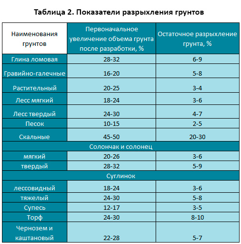
Table 2: Indexes of soil loosening
| Soil names | Initial increase in soil volume after development, % | Residual loosening of soil, % |
| Lot clay | 28...32 | 6...9 |
| gravel and pebble | 16...20 | 5...8 |
| Vegetable | 20...25 | 3...4 |
| Loess soft | 18...24 | 3...6 |
| Loess solid | 24...30 | 4...7 |
| Sand | 10...15 | 2...5 |
| rocky | 45...50 | 20...30 |
| Salt marsh and solonetz | ||
| soft | 20...26 | 3...6 |
| solid | 28...32 | 5...9 |
| Loam | ||
| light and loess | 18...24 | 3...6 |
| heavy | 24...30 | 5...8 |
| sandy loam | 12...17 | 3...5 |
| Peat | 24...30 | 8...10 |
| Chernozem and chestnut | 22...28 | 5...7 |
Normative values of the steepness of slopes for temporary earthworks are given in Table. 3. If the excavation depth is more than 5 m, the steepness of the slopes is established by the project. The slopes of permanent structures are made flatter than the slopes of temporary structures, and are not less than 1:1.5.
The water-holding capacity or resistance of a soil to water penetration is very high in clay soils and low in sandy soils. For this reason, the latter are called draining, i.e. well-permeable water, and the first - non-draining.
The drainage capacity of soils is characterized by a filtration coefficient K equal to 1...150 m/day.
Table 3: Steepness of slopes depending on the type of soil and the depth of excavation
As a result of earthworks, earthworks are created, which are classified according to a number of criteria.
According to the purpose and duration of operation, earthworks are divided into permanent and temporary.
Permanent structures are designed for long-term use. These include canals, dams, dams, planned sites for residential areas, complexes of industrial buildings, stadiums, airfields, excavation and embankment of the subgrade of roads, the construction of reservoirs, etc.
Temporary earthworks are those that are erected only for the period of construction. They are intended for the placement of technical facilities and the performance of construction and installation work on the construction of foundations and underground parts of buildings, laying underground utilities, etc.
A temporary excavation having a width of up to 3 m and a length significantly exceeding the width is called a trench. A recess, the length of which is equal to the width or does not exceed ten times its size, is called a foundation pit. Pit pits and trenches have a bottom and side surfaces, inclined slopes or vertical walls.
The division of earthworks into permanent and temporary is necessary, since they are subject to various requirements regarding the stability of slopes, the thoroughness of their compaction and finishing, and ensuring the watertightness of the excavation body.
According to the location of earthworks relative to the surface of the earth, they differ: excavations - depressions formed by excavation of soil below the surface level; embankments - elevations on the surface, erected by dumping previously developed soil; cavaliers - embankments formed when dumping unnecessary soil, as well as for temporary storage of soil, backfilling trenches and foundations.
The most characteristic profiles and elements of earthworks are shown in fig. 1.1.
Rice. 1.1. Types of earthworks:
b- a pit (trench) of a trapezoidal shape;
in– profile of permanent excavation; 1 - slope edge; 2 - slope; 3 - berm;
G- round; d- rectangular; III- embankment profiles;
e - temporary embankment; and- permanent; IV- backfilling;
h- sinuses of the pit; and– trenches
Temporary excavations closed from the surface and arranged for the construction of transport and utility tunnels and other purposes are called underground workings.
After the construction of the underground parts of the buildings, the soil from the dump (cavalier) is placed in the so-called "bosoms" - the spaces between the side surface of the structure and the slopes of the pit (trench). If the dumping of soil from the dump is used to completely cover the underground part of the building or communications, it is called backfilling.
Compliance with the purpose and reliability in the operation of earthworks is ensured by compliance with a set of requirements for design and construction. All earthworks must be stable, durable, able to withstand design loads, withstand climatic influences (precipitation, negative temperatures, weathering, etc.), have a configuration and dimensions in accordance with the project and maintain them during operation. The requirements for earthworks in specific conditions are established by the project in accordance with the norms of building design.
Determining the volume of developed soil
For the main production processes, the volumes of the developed soil are determined in cubic meters in a dense body. For some preparatory and auxiliary processes (surface plowing, slope planning, etc.), volumes are determined in square meters of surface.
The calculation of the volumes of the developed soil is reduced to determining the volumes of various geometric shapes that determine the shape of a particular earthwork. It is assumed that the volume of soil is limited by planes and individual irregularities do not affect the accuracy of the calculation.
In the practice of industrial and civil construction, it is mainly necessary to calculate the volumes of pits, trenches ( and other extended structures) and the volumes of excavations and embankments in the vertical layout of the sites.
Determination of volumes in the development of pits and trenches
The pit is, from a geometric point of view, an obelisk ( fig.3.12), the volume of which V calculated according to the formula: V =H / (2a+a1)b + (2a1+a)b1/6,
where H- the depth of the pit, calculated as the difference between the arithmetic mean mark of the top of the pit in the corners (marks of the terrain in the area of the planning embankment and the design mark in the area of the planning excavation) and the mark of the bottom of the pit; a, b- the lengths of the sides of the pit (taken equal to the dimensions of the lower part of the foundation at the base with a working gap of about 0.5 m on each side), a \u003d a "+ 0.5 2, b \u003d b" + 0.5 2; a",b"- the dimensions of the lower part of the foundation; a1, b1- the length of the sides of the pit on top, a1 = a + 2H m; b1 = 2H m; m- slope coefficient (normative value according to SNiP).

Fig.3.12. Determining the volume of the pit:
a- geometric scheme for determining the volume of the pit; b- section of the permanent pit (slope 1:2) and temporary (slope 1:1); 1 – excavation volume; 2 - backfill volume
To determine the volume of backfilling of the sinuses of the pit, when its volume is known, it is necessary to subtract the volume of the underground part of the structure from the volume of the pit Vob.z \u003d V - (a "b") N.
When calculating the volumes of trenches and other linearly extended structures, their projects should include longitudinal and transverse profiles. The longitudinal profile is divided into sections between the fracture points along the bottom of the trench and the day surface. For each such section, the volume of the trench is calculated separately, after which they are summarized. A trench, an extended cut and an embankment in the area between points 1 and 2 are a trapezoidal prismatoid (Fig. 3.13), the volume of which can be approximately determined:
V1-2 = (F1+F2) L1-2/2(inflated)
V1-2 = Fav L1-2(understated),
where F1, F2 are the cross-sectional areas at the corresponding points in the longitudinal profile, defined as F = aH + H2m; Fav- cross-sectional area at the middle of the distance between points 1 and 2.
 Rice. 3.13. Scheme for determining the volume of the trench
A more accurate value of the volume of the prismatoid is found by the formulas:
V1-2 = Fav + L1-2,
V1-2 = L1-2.
Calculation of the volume of planning work produced either by the method of triangular prisms, or by the average mark of the squares.
In the first method, the planned site is divided into squares with a side (depending on the terrain) of 25-100 m; the squares are divided into triangles, at the vertices of which the working marks of the layout are written out (Fig. 3.14, a).
If the marks (H1, H2, H3) have the same sign (cut or fill),
the volume of each prism (Fig. 3.14, b) is determined by the formula:
V \u003d a² / 6 (H1 + H2 + H3).
With different signs of working marks (Fig. 3.14, c), the calculation according to this formula gives the total volume of filling and excavation; separate volumes can be obtained by subtracting the pyramid volume ABCD from the total volume of the ADHYGE prism.
Rice. 3.14. Volume calculation scheme
earthwork method
triangular prisms:

a- breakdown of the site (the numbers in circles are the numbers of prisms; the numbers on the
section of lines - working marks);
b- triangular prism at working
marks of one character; in- also with different marks 
Average mark method
squares, planning volumes are calculated using a plan with horizontal lines of 0.25–0.5 m for flat and 0.5–1 m for mountainous areas.
A grid of squares with a side of 10–50 m and the lines of the boundaries of embankments and excavations are applied to the plan. The volume of the layout of each square is calculated based on the average square of the working marks of the layout.
The volume of embankments and excavations of linear structures(roads, canals) on the straight sections of the structure is usually determined by auxiliary tables.
For buildings with curved axis(Fig. 3.15) you can use the Gulden formula: V= (F⋅π⋅ r⋅α)/180º;
where V- volume of earthwork, m3, F- cross-sectional area, m2,
r- radius of curvature of the axis of the body of the earthen structure, m,α- central angle
turning the extreme profiles limiting the curved section, hail.
Calculating the volume of earthen cones for artificial structures:
With the same steepness of the slope of the subgrade and the slope of the cone - according to the formula:
V=π H/24;
where V1 is the volume of both cones, m3, N- the height of the embankment in the section along the edge of the foundation, m, b- the width of the canvas, m, b1- abutment width, m- slope indicator
subgrade and cones,


Rice. 3.15. Linear earthwork with Fig.3.16. Subgrade slopes
curved axisat bridge cones.
With different steepness of the slope of the subgrade and the slope of the cone (Fig. 3.16)
- according to the formula: V 1= π H/6· [ 3(b- b1)/2· (x-α ) +1.5 ( b- b1)/2· nH+1.5(x-α)· mH+mnH² ;
where n- indicator of the slope of the cone, x- the full value of the entry of the subgrade -
on the abutment at the level of the brow, m,α - the value of the entry of the rectilinear part
earthen bed, m.
Cabinetmaker. In 1921 he became one of the founders of the Communist...

Slavic culture, although different from Indian, and even more so from Tibetan, ...

History of Bohemia HISTORIA BOHEMICA Among the chronicles covering the history of the Czech Republic...